2.2 Object Model
Objects common to both the needs of Store-and-forward and Real-time stream
broadcasts are Channel, Configuration, Schedule, Transmission and Business
Rule objects. Channel objects define the characteristics of channels within
the transponder bandwidth. Configuration objects define the required number
and device types (pools) to satisfy a service offering. Contractual agreements
bind Channel objects to Configuration objects in a many-to-many relationship
allowing for schedule optimization of resources and schedule robustness. |
|
A Schedule object reflects a commitment to provide service at a specified
time or within service time definition. Schedule objects are, in essence,
an abstract class that has specific sub-classes depending on service requirements.
The currently defined sub-classes are Store-and-forward, Real-time Stream
and Maintenance. Maintenance is a special case described below.
Transmission objects provide for the management of Schedule objects
as they transition to actual transmission events. This occurs when the
schedule time for the object nears. For Store-and-forward Schedule objects,
this occurs automatically since operator intervention is not required while
with Real-time Stream Schedule objects, an Uplink Center operator initiates
the transition at schedule time.
A Business Rule object allows the specification of attributes that define
operational constraints on the system such as hours of operation and maximum
and minimum schedule durations by service. For the most part, they are
used to optimize the scheduling engine. This was chosen to provide loose
coupling between the system applications and the requirement for operators
to be able to simply define new or changes to operational constraints.
Additional objects to support specific requirements for Store-and-forward
services and for the maintenance of Uplink Center equipment are also managed.
For Store-and-forward service, a Data object is provided for the management
of the customer's data files. This object defines the metadata associated
with the data file and is associated with a specific Schedule object for
transmission. Similarly, Maintenance objects are a type of Schedule object
that do not reflect a transmission but effectively block the use of devices
for schedules by taking them out-of-service for a specified time. This
is done to maintain a consistent view of the system and allow for the uniform
management of Schedule objects. Store-and-forward items affected by the
Maintenance object are automatically rescheduled if possible. |
There are three types of Configuration objects:
-
Product, which define the general service offerings through the combination
of resource pools,
-
User, which allow for the specialization of Product configurations to a
customer's needs and;
-
Scheduled, which bind specific devices from pools, along with assigned
channel, to a scheduled trans-mission.
|
|
|
3. Workflow Technology in a Broadcast Management System
As the system exists today, the interaction of the object model specification
and the scheduling engine can be thought of, roughly, as a workflow application
being executed by a workflow engine, if we expand the concepts frequently
promoted as part of workflow technology [GHS95, JBu96]. For example, the
notions of time durability in our satellite transmission scheduling problem
requires that real-time and temporal concepts be integrated into workflow
systems. It also suggests that more flexible scheduling of workflow tasks
to produce execution patterns which parallelize and optimize task execution
and utilize existing resources to their fullest capacity, while still operating
within system and business con-straints (currently captured in the object
model) is required.
Furthermore, because there are a number of products and services that
can be configured from this basic satellite transmission infrastructure,
it is important to create, and automate where appropriate, business processes
to efficiently manage multiple transmission events, each with different
time, information, and transmission constraints. Workflow technology provides
a useful execution framework for such processes, and we are exploring it
as a mechanism to implement some components of a monitoring function required
for broadcast management. This capability is particularly important in
event-driven applications such as information dissemination for integrated
battle management.
In the discussion that follows, we first summarize a high-level view
of the business process used in this particular on-demand broadcast service.
This provides the context for a discussion of how a subprocess can be automated
using a workflow engine, and what extensions are required to integrate
the workflow management sys-tem (WFMS) with our existing transmission scheduling
engine. This illustrates specifically one way in which temporal information
can be used as a guide for the scheduling of a workflow execution, and
motivates design changes to a WFMS that will allow workflow tasks to be
scheduled more flexibly. Lastly, we conclude the section with a discussion
of other information dissemination techniques can be integrated as well. |
3.1 System Business Process
The system business processes, shown in Figure 3, illustrate the major
process components (denoted by different colors) and information flow (shown
as labels on the arcs between nodes) through the system. Customer Management
consists of Product Management, Contract Management and Billing. Provisioning
consists of Resource Management, Channel Management, Product Configuration
and Customer Configuration. Scheduling is a stand-alone process as is Schedule
Execution.
The Product Management process defines the product offerings according
to service characteristics and pricing. Service offerings can be negotiated
with customers to respond to specific needs outside of the normal offerings.
This is part of the Contract Management process. Contract Management is
the process of setting up customer information and profiles after sales
are completed. Billing is the process of converting service activities
into invoices.
Resource Management defines the physical components and their characteristics
in the uplink center. Channel Management identifies the types and characteristics
of service channels in the uplink center. Product Configuration is the
process of taking product definitions and allocating resource types to
the definition. Upon the definition of a contract, the Customer Configuration
process creates customer specific instances of product configurations and
assigns allowable channels to the configuration. Resource types can also
be converted to specific devices within the resource pools for that customer
instance. At this point, the system has sufficient information to allow
customers to schedule transmissions.
|
Figure 3: System Business Process Model
Scheduling is the process of customers identifying the contract information
relative to billing assignments, identifying the specific customer configuration
desired to be scheduled, and specifying the desired time for the transmission.
Schedule Execution does the necessary Uplink center physical configuration
at the requested transmission time and monitors the state of the transmission.
For Store-and-forward services, operator intervention is not required while
Real-time Stream services require the intervention of operators to connect
patch cables, handle tape machines and provide other related services.
At the completion of transmission, a charge record is generated for use
by the billing process.
3.2 Customer Order Processing Workflow
Workflow management systems are specifically designed to provide the capability
of managing work, especially if there is some specific order in the tasks
people have to perform to reach a result. In this product offering, a successful
result means that the transmission of data or a video took place as scheduled
according to the customer's specification.. As an example, we describe
here the execution of a customer order workflow type called customer order
processing, shown graphically in Figure 4; it is a refined subset of the
high-level processes just described. For each customer request, this workflow
type is instantiated and executed by a workflow engine. |
Figure 4: An Example Workflow Type
|
The figure does not show the complete workflow specification but is
restricted to the most important as-pects of it. When a customer calls
and wants to place an order for transmitting data, a customer representative
ini-tiates a customer order processing workflow instance. The customer
representative is then assigned the first step of the workflow instance:
input customer order. This step brings up an application program with a
graphical user interface. The customer representative asks the customer
the details of the order, such as what information should be transmitted
and when the transmissions should take place (year, month, day and time
of transmissions as well as the duration of the transmission)2.
In addition billing information is captured.
Before an order can be placed, the order has to be scheduled. This is
necessary since a transmission uses resources which are of limited availability
(e.g. a tape drive). Depending on the resource demands of the order and
the resource availability at the requested transmission time, the order
will be placed or denied by the customer representative. The scheduling
of the required resources is done by a dedicated resource scheduling system,
such as the scheduling engine just described for the current prod-uct offering.
If the resources are available, the order is placed and the step input
customer order is done. The order data (order) are also transferred to
the next step in the workflow (transmit data). If required resources are
not available, the customer might decide to ask for an-other time of transmission
or to not place an order at all. In the latter case the customer representative
discards the order ("order discarded by customer") and the workflow instance
is finished as a whole.
The functionality of a workflow system is especially useful for prompting
users to perform manual tasks in a complex process. The most obvious example
in the on-demand broadcast application is the manual set-up re-quired for
some transmissions. The workflow system can provide a list of jobs for
an Uplink center operator to carry out. After the set-up, the operator
initiates the transmission using an application program. If the trans-missions
fails, no billing record is written and the workflow instance finishes
("failure during transmis-sion"). At this point the workflow type is simplified.
Usually the customer has to be notified of the failure and some compensation,
such as retransmission, is negotiated.
If the transmission succeeds, the order information, together with the
actual transmission data, are transferred to the step write billing record.
This step then takes the data and writes a billing record into a billing
database. This step is executed by another application program. Since computing
the amount to be charged and storing the information can be fully automated,
this step is done automatically. This step is the last step in the workflow
instance, after which the instance is deleted from the system.
2 Note that this process of getting customer input could
be automated via electronic user profiles for information services that
require recurring or refresh broadcasts. |
.
3.3 Transmission-Driven Workflow Schedules
Current workflow management systems assign workflow instances to a role
(and subsequently to people or automated agents) according to the control
flow and data flow specified in the workflow type. For example, the step
transmit data is assigned to an operator as soon as the step input customer
order is finished. This results in all outstanding orders being listed
in the worklists of the operators.
Since orders can be placed in advance, the list of out-standing transmissions
could be long. Certainly, if the orders are generated via automatic profile
analysis in a smart push architecture [DPe96], the queue of scheduled transmissions
could be extremely large. However, an op-erator who is working shifts does
not want to see transmission orders that do not take place during a particular
shift at all. Instead, they should be provided a view of only those outstanding
orders to be executed in that shift. There are basically two ways to achieve
this:
1. Extend the functionality of a worklist such that the worklist can
query all transmission orders between two given points in time, i. e. the
start and finish time of a shift. An operator would type in the shift starting
time and the worklist would only display the appropriate assignments. This
would require that the transmission start and end time is available to
the corresponding workflow instance, and could be implemented by storing
these values in addition to the order identifier in the workflow instance.
2. The workflow management system does not instantiate the second step
transmit data right after the first step input customer order has finished,
and therefore does not assign the work to an operator worklist. Since it
is known when a transmission has to take place, the workflow management
system could postpone the instantiation of the second step until some time
just before the scheduled transmission, e.g. two hours, at which time the
transmission would appear in the worklist. In this case, the workflow management
system has to be able to schedule parts of the execution of the workflow
instance itself based on the output of the transmission scheduling engine
(i.e. the transmis-sion schedule)3.
At first glance, the first solution is appealing since little additional
functionality is required. The worklist has to be extended to search for
workflow instances with certain attribute values: in this case, the start
and end time of transmission. The definition of the attribute values in
the workflow type and the assignment of their values is specified by the
workflow designer. However, due to the potentially large set of transmission
requests in the system, this approach has the drawback of inefficiency
by maintaining many workflow instances for pending transmissions. It would
also lead to more complicated recovery mechanisms for instantiated workflows
in the event of a system failure.
The second case does have the drawback of creating additional functionality
within the WFMS. However, it may be more advantageous since workflow instances
do not exist until shortly before their use, and hence, WFMS resources
are used more efficiently. At the same time, failure recovery can be easier
and faster since the number of workflow instances to be restored is much
lower.
3 Note that this scheduling process is different from the
transmission schedule itself. Here, we are focused on the scheduling events
required to manage the transmission sched-ule, not determine the transmission
schedule itself. |
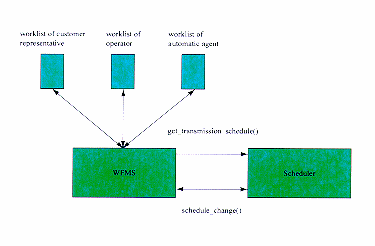
Figure 5: Interoperable WFMS and Transmission Scheduler
|
|
3.4 Interoperability Architecture for Transmission and Workflow Engines
We propose an architecture, shown in Figure 5, to enable the creation of
workflow instances depending on schedule of transmission orders that can
be used to implement the second solution proposed above. The important
observation is that workflow instances are not scheduled according to the
static steps in the workflow specification (i.e. Figure 4), but instead
according to the transmission order schedule.
To do this, the WFMS must communicate with the transmission scheduling
system. As soon as the step input customer order is successfully finished,
the WFMS determines the time window of the scheduled transmission using
the function "get_transmission_schedule(transmission_id)" of the transmission
scheduler. The WFMS then creates a scheduled workflow instance. This is
not a workflow instance itself but an entry within its database indicating
when a workflow instance of the step transmit data has to be created. The
WFMS polls periodically (or based on a time interrupt service) the scheduled
workflow instances and creates them accordingly. For those instances which
require manual set-up, the workflow instance can be created so that it
will appear in the worklist of the operator at some default period of time
(e.g. two hours) before the actual transmission time.
While there are existing WFMS that can start workflow instances at a
given time [COS94], the infor-mation has to be supplied by a user. However,
in our proposed architecture, the WFMS is tightly integrated with a dedicated
transmission scheduler on an application programming interface (API) level.
In this approach, the system can determine when to schedule a workflow
instance and not rely on manual work.
One of the advantages of this approach is apparent for applications
that require frequent re-scheduling, auto-matic refresh broadcasts based
on user profiles, or other event-driven transmissions. The dedicated scheduler
can actively notify the WFMS about a schedule change. Subsequently the
WFMS can adjust its scheduled workflow instances.
Several cases of rescheduling have to be considered.
-
The new schedule is after the current time. In this case no problem arises
and the workflow can be in-stantiated according to the new schedule.
-
The new schedule starts at the current time. In this case the instantiation
occurs immediately. The WFMS does not have to change its entry for the
scheduled entry, but has to delete it when done.
-
The new schedule is before the current time. In this case the schedule
change is too late: this scenario might arise in the case of equipment
failure, for ex-ample. There are a number of ways to handle this case.
One way is the workflow instance is created even though it is too late.
In the current product offering, this is not allowed since a customer asked
for a specific fixed schedule. Another possibility is to delete the scheduled
workflow since it will never be executed. However, this is not a feasible
approach since the customer still needs to be notified. Even though the
step transmit data will not be executed, the overall workflow customer
order processing must continue with notification and renegotiation with
the customer. In this case, a step contact customer could be instantiated.
|
3.5 Information Dissemination Techniques as Scheduling Events
The triggering event for the execution of the transmit data workflow step
in the current on-demand transmission service is an a-priori content provider
request, however, others need to be incorporated. In applications such
as a weather service, receivers require updated information at some (a)periodic
rate of delivery [FZd96, SRB97]. Other parameters that could determine
transmission events in-clude frequency of update, the size of the changed
information, the number of receive sites interested in the updates, and
new requests for information. For highly dynamic application domains, such
as integrated battle management, the frequency of updates to source data
can vary widely: from the nanosecond range for sensor infor-mation, for
example, to hourly updates to intelligence databases. Furthermore, information,
such as battle plans, may only be valid for a certain, and relatively short,
period of time. In the case of smart push [DPe96], one or more intermediary
servers are used to aggregate receive site profiles to determine how best
to package source in-formation for broadcast. This profile information
itself is also subject to update, and brings another layer of data consistency
to be maintained. A transmission scheduler must optimize to these parameters
and the resulting schedules must be flexibly accommodated by a broadcast
management system, possibly implemented with an extended workflow management
infrastructure.
|
Summary
We have described a commercial on-demand satellite broadcast system, including
its operational model and system components, and the business process used
for the service configuration. The current system is implemented by a database
driven scheduling engine that will provide the core functionality of future
services. We have discussed some of the issues in the design of a broadcast
management system by integrating a transmission scheduling system with
a workflow management infrastructure. Future work will focus a more detailed
study of how in-formation dissemination techniques can be incorporated
and on their effect on the integrated design of a broadcast management
system for different satellite-based information systems. |
Acknowledgments
The authors gratefully acknowledge the contributions of the rest of the
DigitalXpress team, especially Tom Haug, Doug Julien and Joel Wright, for
their significant contributions to the design and implementation of the
system, and insightful comments on this paper. We would also like to note
that the recent passing of our colleague Art Murphy, whose work on the
scheduling engine reported here, is a significant personal and professional
loss; we plan to continue his research agenda to the best of our ability.
|
|
|
References
|
|
|
[COS94]
|
COSA programming manual, Software-Ley GmbH, Pulheim, Germany, 1994. |
|
[DPe96]
|
Dao, S., Perry, B., "Information Dissemination in Hybrid Satellite/Terrestrial
Networks", IEEE Data Engineering Bulletin, Vol. 19, No. 3, pp.12-18, Sept.
1996. |
|
[FZd96]
|
Franklin, M., Zdonik, S., "Dissemination-Based Information Systems",
IEEE Data En-gineering Bulletin, Vol. 19, No. 3, pp.20-30, Sept. 1996. |
|
[GHS95]
|
Georgakopoulos, D., Hornik, M., Sheth, A., "An Overview of Workflow
Management: From Process Modeling to Workflow Automa-tion Infrastructure",
Distributed and Parallel Databases, No. 3, 1995. |
|
[Hug97]
|
Hughes Network Systems. DirecPC Home-page. http://www.direcpc.com. |
|
[JBu96]
|
Jablonski, S., Bussler, C., "Workflow Management. Modeling Concepts,
Architecture and Implementation", International Thomson Computer Press,
1996. |
|
[SRB97]
|
Stathatos, K., Roussopoulos, N., Baras, J., "Adaptive Data Broadcast
in Hybrid Net-works", Proceedings of the 23rd International Conf. On Very
Large Data Bases, pp.326-335, Athens Greece, Aug. 1997. |