Over the past several years there have been many implementations of expert systems using various tools and various hardware platforms, from powerful LISP machine workstations to smaller personal computers.
The technology has left the confines of the academic world and has spread through many commercial institutions. People wanting to explore the technology and experiment with it have a bewildering selection of tools from which to choose. There continues to be a debate as to whether or not it is best to write expert systems using a high-level shell, an AI language such as LISP or Prolog, or a conventional language such as C.
This book is designed to teach you how to build expert systems from the inside out. It presents the various features used in expert systems, shows how to implement them in Prolog, and how to use them to solve problems.
The code presented in this book is a foundation from which many types of expert systems can be built. It can be modified and tuned for particular applications. It can be used for rapid prototyping. It can be used as an educational laboratory for experimenting with expert system concepts.
Expert systems are computer applications which embody some non-algorithmic expertise for solving certain types of problems. For example, expert systems are used in diagnostic applications servicing both people and machinery. They also play chess, make financial planning decisions, configure computers, monitor real time systems, underwrite insurance policies, and perform many other services which previously required human expertise.

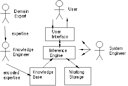
Figure 1.1 Expert system components and human interfaces
Expert systems have a number of major system components and interface with individuals in various roles. These are illustrated in figure 1.1. The major components are:
• Knowledge base - a declarative representation of the expertise, often in IF THEN rules;
• Working storage - the data which is specific to a problem being solved;
• Inference engine - the code at the core of the system which derives recommendations from the knowledge base and problem-specific data in working storage;
• User interface - the code that controls the dialog between the user and the system.
To understand expert system design, it is also necessary to understand the major roles of individuals who interact with the system. These are:
• Domain expert - the individual or individuals who currently are experts solving the problems the system is intended to solve;
• Knowledge engineer - the individual who encodes the expert's knowledge in a declarative form that can be used by the expert system;
• User - the individual who will be consulting with the system to get advice which would have been provided by the expert.
Many expert systems are built with products called expert system shells. The shell is a piece of software which contains the user interface, a format for declarative knowledge in the knowledge base, and an inference engine. The knowledge engineer uses the shell to build a system for a particular problem domain.
Expert systems are also built with shells that are custom developed for particular applications. In this case there is another key individual:
• System engineer - the individual who builds the user interface, designs the declarative format of the knowledge base, and implements the inference engine.
Depending on the size of the project, the knowledge engineer and the system engineer might be the same person. For a custom built system, the design of the format of the knowledge base, and the coding of the domain knowledge are closely related. The format has a significant effect on the coding of the knowledge.
One of the major bottlenecks in building expert systems is the knowledge engineering process. The coding of the expertise into the declarative rule format can be a difficult and tedious task. One major advantage of a customized shell is that the format of the knowledge base can be designed to facilitate the knowledge engineering process.
The objective of this design process is to reduce the semantic gap. Semantic gap refers to the difference between the natural representation of some knowledge and the programmatic representation of that knowledge. For example, compare the semantic gap between a mathematical formula and its representation in both assembler and FORTRAN. FORTRAN code (for formulas) has a smaller semantic gap and is therefor easier to work with.
Since the major bottleneck in expert system development is the building of the knowledge base, it stands to reason that the semantic gap between the expert's representation of the knowledge and the representation in the knowledge base should be minimized. With a customized system, the system engineer can implement a knowledge base whose structures are as close as possible to those used by the domain expert.
This book concentrates primarily on the techniques used by the system engineer and knowledge engineer to design customized systems. It explains the various types of inference engines and knowledge bases that can be designed, and how to build and use them. It tells how they can be mixed together for some problems, and customized to meet the needs of a given application.
There are a number of features which are commonly used in expert systems. Some shells provide most of these features, and others just a few. Customized shells provide the features which are best suited for the particular problem. The major features covered in this book are:
• Goal driven reasoning or backward chaining - an inference technique which uses IF THEN rules to repetitively break a goal into smaller sub-goals which are easier to prove;
• Coping with uncertainty - the ability of the system to reason with rules and data which are not precisely known;
• Data driven reasoning or forward chaining - an inference technique which uses IF THEN rules to deduce a problem solution from initial data;
• Data representation - the way in which the problem specific data in the system is stored and accessed;
• User interface - that portion of the code which creates an easy to use system;
• Explanations - the ability of the system to explain the reasoning process that it used to reach a recommendation.
Goal-driven reasoning, or backward chaining, is an efficient way to solve problems that can be modelled as "structured selection" problems. That is, the aim of the system is to pick the best choice from many enumerated possibilities. For example, an identification problem falls in this category. Diagnostic systems also fit this model, since the aim of the system is to pick the correct diagnosis.
The knowledge is structured in rules which describe how each of the possibilities might be selected. The rule breaks the problem into sub-problems. For example, the following top level rules are in a system which identifies birds.
IF
family is albatross and
color is white
THEN
bird is laysan albatross.
IF
family is albatross and
color is dark
THEN
bird is black footed albatross.
The system would try all of the rules which gave information satisfying the goal of identifying the bird. Each would trigger sub-goals. In the case of these two rules, the sub-goals of determining the family and the color would be pursued. The following rule is one that satisfies the family sub-goal:
IF
order is tubenose and
size large and
wings long narrow
THEN
family is albatross.
The sub-goals of determining color, size, and wings would be satisfied by asking the user. By having the lowest level sub-goal satisfied or denied by the user, the system effectively carries on a dialog with the user. The user sees the system asking questions and responding to answers as it attempts to find the rule which correctly identifies the bird.
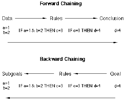
Figure 1.2. Difference between forward and backward chaining
Often times in structured selection problems the final answer is not known with complete certainty. The expert's rules might be vague, and the user might be unsure of answers to questions. This can be easily seen in medical diagnostic systems where the expert is not able to be definite about the relationship between symptoms and diseases. In fact, the doctor might offer multiple possible diagnoses.
For expert systems to work in the real world they must also be able to deal with uncertainty. One of the simplest schemes is to associate a numeric value with each piece of information in the system. The numeric value represents the certainty with which the information is known. There are numerous ways in which these numbers can be defined, and how they are combined during the inference process.
For many problems it is not possible to enumerate all of the possible answers before hand and have the system select the correct one. For example, configuration problems fall in this category. These systems might put components in a computer, design circuit boards, or lay out office space. Since the inputs vary and can be combined in an almost infinite number of ways, the goal driven approach will not work.
|
The data driven approach, or forward chaining, uses rules similar to those used for backward chaining, however, the inference process is different. The system keeps track of the current state of problem solution and looks for rules which will move that state closer to a final solution. |
A system to layout living room furniture would begin with a problem state consisting of a number of unplaced pieces of furniture. Various rules would be responsible for placing the furniture in the room, thus changing the problem state. When all of the furniture was placed, the system would be finished, and the output would be the final state. Here is a rule from such a system which places the television opposite the couch.
IF
unplaced tv and
couch on wall(X) and
wall(Y) opposite wall(X)
THEN
place tv on wall(Y).
This rule would take a problem state with an unplaced television and transform it to a state that had the television placed on the opposite wall from the couch. Since the television is now placed, this rule will not fire again. Other rules for other furniture will fire until the furniture arrangement task is finished.
Note that for a data driven system, the system must be initially populated with data, in contrast to the goal driven system which gathers data as it needs it. Figure 1.2 illustrates the difference between forward and backward chaining systems for two simplified rules. The forward chaining system starts with the data of a=1 and b=2 and uses the rules to derive d=4. The backward chaining system starts with the goal of finding a value for d and uses the two rules to reduce that to the problem of finding values for a and b.
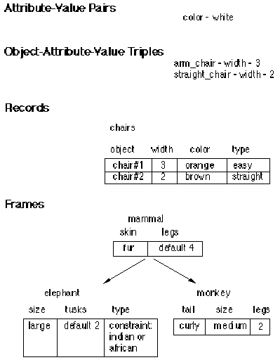
Figure 1.3. Four levels of data representation
For all rule based systems, the rules refer to data. The data representation can be simple or complex, depending on the problem. The four levels described in this section are illustrated in figure 1.3.
The most fundamental scheme uses attribute-value pairs as seen in the rules for identifying birds. Examples are color-white, and size-large.
When a system is reasoning about multiple objects, it is necessary to include the object as well as the attribute-value. For example the furniture placement system might be dealing with multiple chairs with different attributes, such as size. The data representation in this case must include the object.
Once there are objects in the system, they each might have multiple attributes. This leads to a record-based structure where a single data item in working storage contains an object name and all of its associated attribute-value pairs.
Frames are a more complex way of storing objects and their attribute-values. Frames add intelligence to the data representation, and allow objects to inherit values from other objects. Furthermore, each of the attributes can have associated with it procedures (called demons) which are executed when the attribute is asked for, or updated.
In a furniture placement system each piece of furniture can inherit default values for length. When the piece is placed, demons are activated which automatically adjust the available space where the item was placed.
The acceptability of an expert system depends to a great extent on the quality of the user interface. The easiest to implement interfaces communicate with the user through a scrolling dialog as illustrated in figure 1.4. The user can enter commands, and respond to questions. The system responds to commands, and asks questions during the inferencing process.
More advanced interfaces make heavy use of pop-up menus, windows, mice, and similar techniques as shown in figure 1.5. If the machine supports it, graphics can also be a powerful tool for communicating with the user. This is especially true for the development interface which is used by the knowledge engineer in building the system.
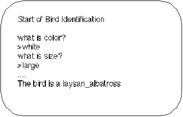
Figure 1.4. Scrolling dialog user interface
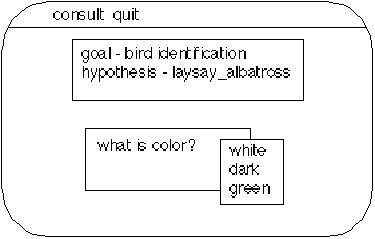
Figure 1.5. Window and menu user interface
One of the more interesting features of expert systems is their ability to explain themselves. Given that the system knows which rules were used during the inference process, it is possible for the system to provide those rules to the user as a means for explaining the results.
This type of explanation can be very dramatic for some systems such as the bird identification system. It could report that it knew the bird was a black footed albatross because it knew it was dark colored and an albatross. It could similarly justify how it knew it was an albatross.
At other times, however, the explanations are relatively useless to the user. This is because the rules of an expert system typically represent empirical knowledge, and not a deep understanding of the problem domain. For example a car diagnostic system has rules which relate symptoms to problems, but no rules which describe why those symptoms are related to those problems.
Explanations are always of extreme value to the knowledge engineer. They are the program traces for knowledge bases. By looking at explanations the knowledge engineer can see how the system is behaving, and how the rules and data are interacting. This is an invaluable diagnostic tool during development.
In chapters 2 through 9, some simple expert systems are used as examples to illustrate the features and how they apply to different problems. These include a bird identification system, a car diagnostic system, and a system which places furniture in a living room.
Chapters 10 and 11 focus on some actual systems used in commercial environments. These were based on the principles in the book, and use some of the code from the book.
The final chapter describes a specialized expert system which solves Rubik's cube and does not use any of the formalized techniques presented earlier in the book. It illustrates how to customize a system for a highly specialized problem domain.
The details of building expert systems are illustrated in this book through the use of Prolog code. There is a small semantic gap between Prolog code and the logical specification of a program. This means the description of a section of code, and the code are relatively similar. Because of the small semantic gap, the code examples are shorter and more concise than they might be with another language.
The expressiveness of Prolog is due to three major features of the language: rule-based programming, built-in pattern matching, and backtracking execution. The rule-based programming allows the program code to be written in a form which is more declarative than procedural. This is made possible by the built-in pattern matching and backtracking which automatically provide for the flow of control in the program. Together these features make it possible to elegantly implement many types of expert systems.
There are also arguments in favor of using conventional languages, such as C, for building expert system shells. Usually these arguments center around issues of portability, performance, and developer experience. As newer versions of commercial Prologs have increased sophistication, portability, and performance, the advantages of C over Prolog decrease. However, there will always be a need for expert system tools in other languages. (One mainframe expert system shell is written entirely in COBOL.)
For those seeking to build systems in other languages, this book is still of value. Since the Prolog code is close to the logical specification of a program, it can be used as the basis for implementation in another language.
This book is written with the assumption that the reader understands Prolog programming. If not, Programming in Prolog by Clocksin and Mellish from Springer-Verlag is the classic Prolog text. APT - The Active Prolog Tutor by the author and published by Solution Systems in South Weymouth, Massachusetts is an interactive PC based tutorial that includes a practice Prolog interpreter.
An in depth understanding of expert systems is not required, but the reader will probably find it useful to explore other texts. In particular since this book focuses on system engineering, readings in knowledge engineering would provide complementary information. Some good books in this area are: Building Expert Systems by Hayes-Roth, Waterman, and Lenat; Rule-Based Expert Systems by Buchanan and Shortliffe; and Programming Expert Systems in OPS5 by Brownston, Kant, Farrell, and Martin.
Copyright ©1989,2000 Amzi! inc. All Rights Reserved.